


bevel-helical speed reducer sew brake gap MC3RVHF06
${{shopModel.rebate>0?shopModel.discountPriceStr:shopModel.formattedAmount}}
$ {{shopModel.formattedAmount}}
Like
{{item.name}}
Quantity:
Estimated Delivery Date: Jul 19-Jul 19
Frequently Asked Questions
How can I contact customer service?
Do you ship overseas?
How long will it take to get my order?
Specifications
{{item.name}}
{{item.value}}
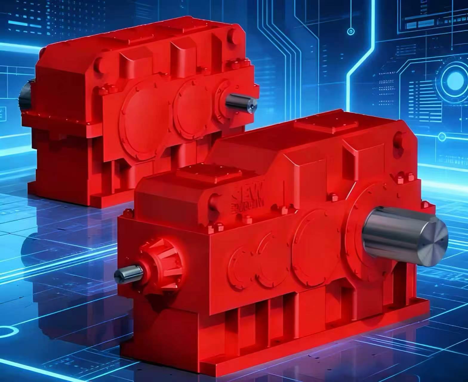
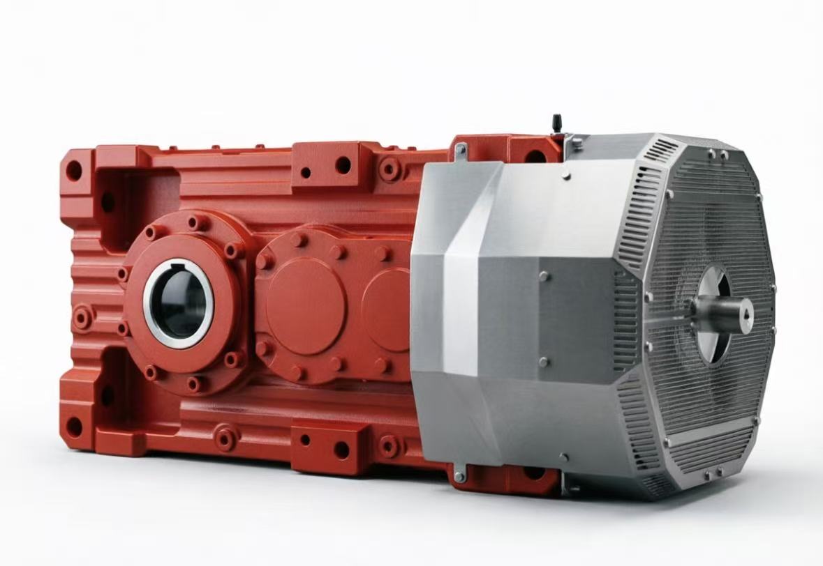
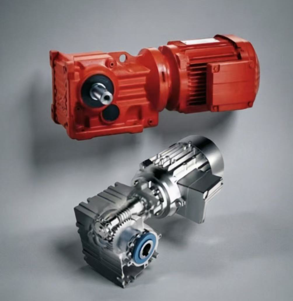
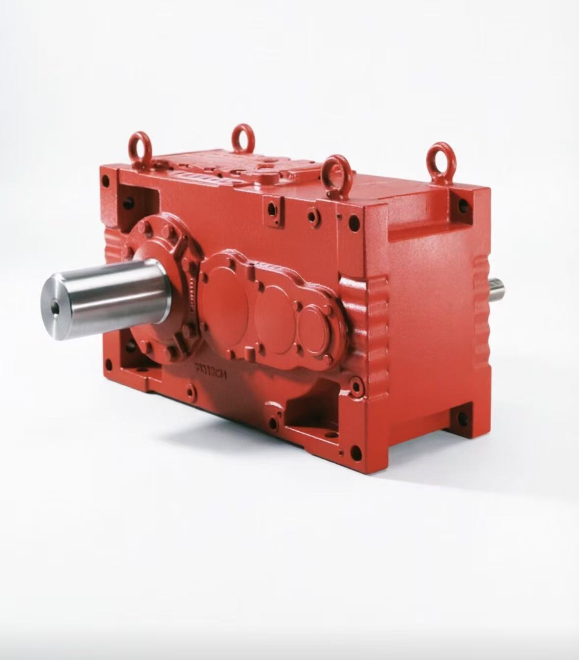
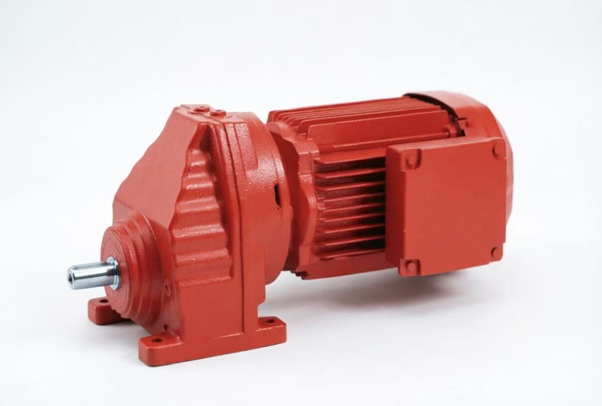
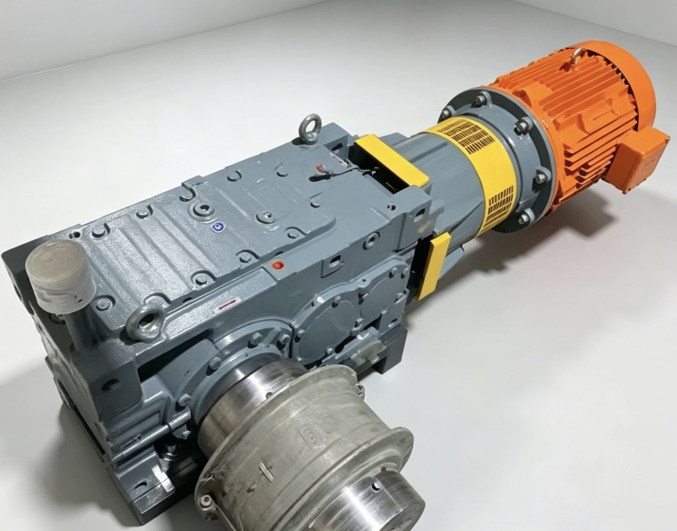
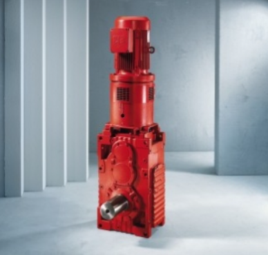
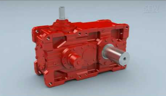
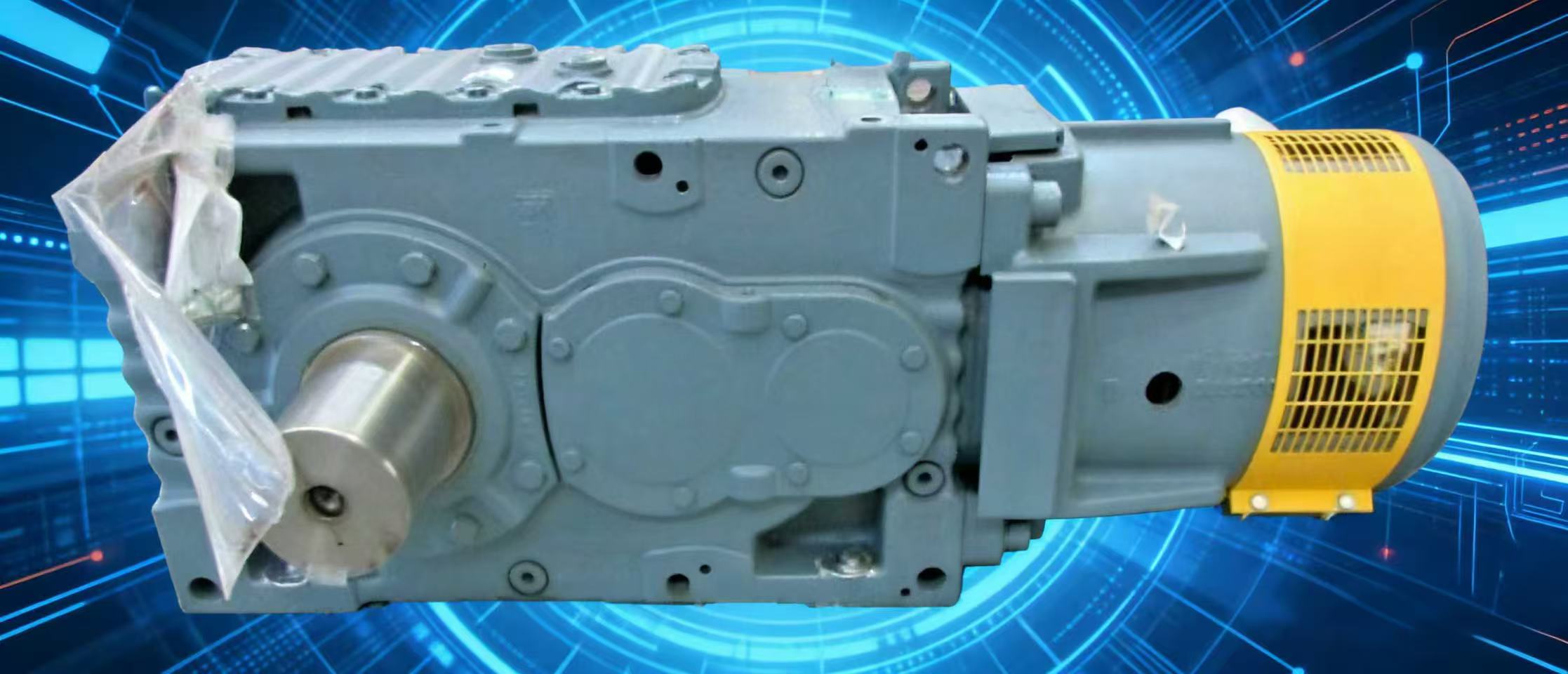
The MC3RVHF06 is a three-stage, bevel-helical industrial gear unit from SEW-EURODRIVE's Medium Compact (MC) series. When paired with an AC motor and a disc brake, maintaining the brake air gap is the most critical maintenance task to prevent motor burnout or gearbox mechanical failure.
Below is a technical guide on the gearbox configuration and the specific procedures for managing the brake gap.
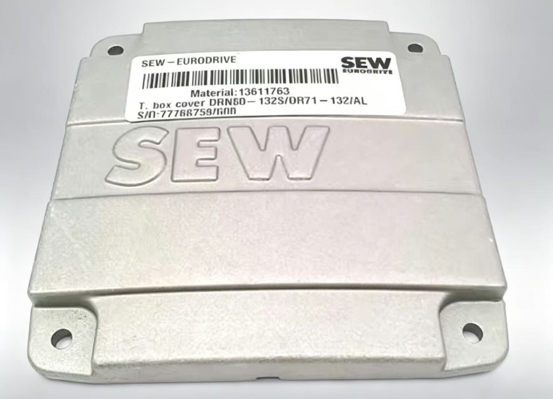
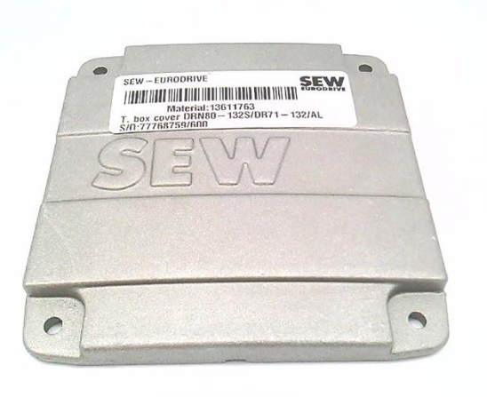
1. Unit Identification: MC3RVHF06
- MC3: Three-stage reduction (Spiral bevel stage + two helical stages). High torque, low output speed.
- R: Bevel-helical (Right-angle) orientation.
- V: Universal mounting housing.
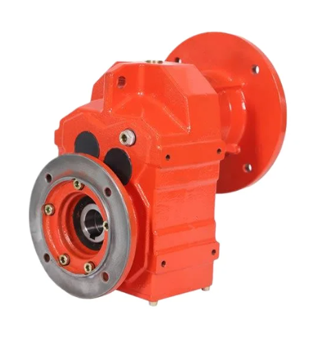
- HF: Hollow shaft with shrink disc and Flange-mounted. This configuration is "shaft-mounted," meaning the gearbox hangs directly on the driven machine's shaft.
- 06: Frame size (Nominal torque capacity around 6,000 to 8,000 Nm).
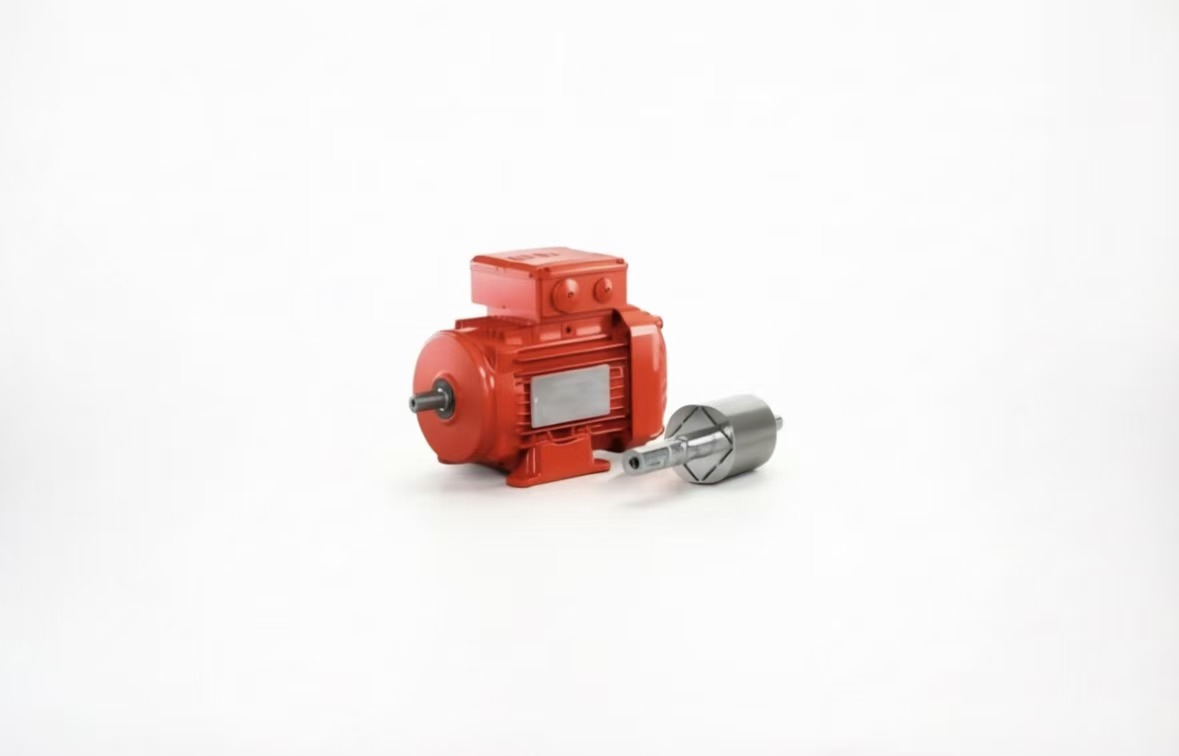
2. Understanding the Brake Air Gap ($g$)
The air gap ($g$) is the physical distance between the brake's stationary electromagnetic coil (pressure plate) and the movable brake disc.
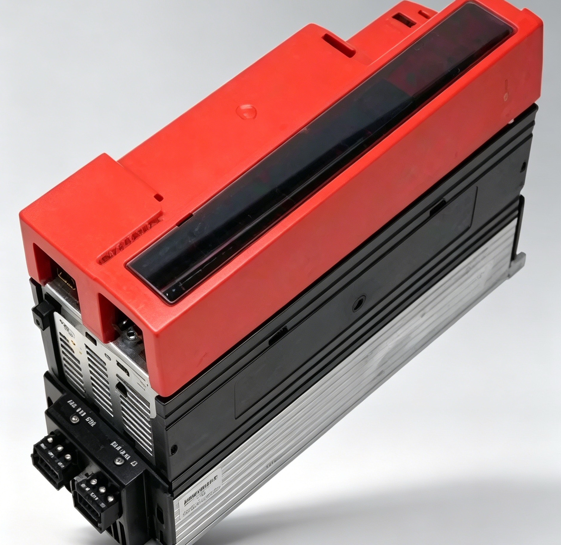
As the brake lining wears down over time through friction, this gap increases. If the gap becomes too wide, the magnetic field generated by the coil (often controlled by a BGE 1.5 rectifier) will not be strong enough to pull the pressure plate back. This results in the brake staying "engaged" while the motor tries to turn, leading to rapid overheating.
Standard Specifications
For the motors typically paired with a Size 06 gearbox (such as the DV or DR series), the following values generally apply:
- Normal Setting: $0.25\text{mm}$ to $0.45\text{mm}$.
- Maximum Limit: Typically $0.8\text{mm}$ to $1.2\text{mm}$ (refer to the motor nameplate for specific limits).
3. How to Measure and Adjust the Gap
[!WARNING]Safety First: Disconnect all power and ensure the load (especially on hoists or inclines) is mechanically secured before opening the brake cover.
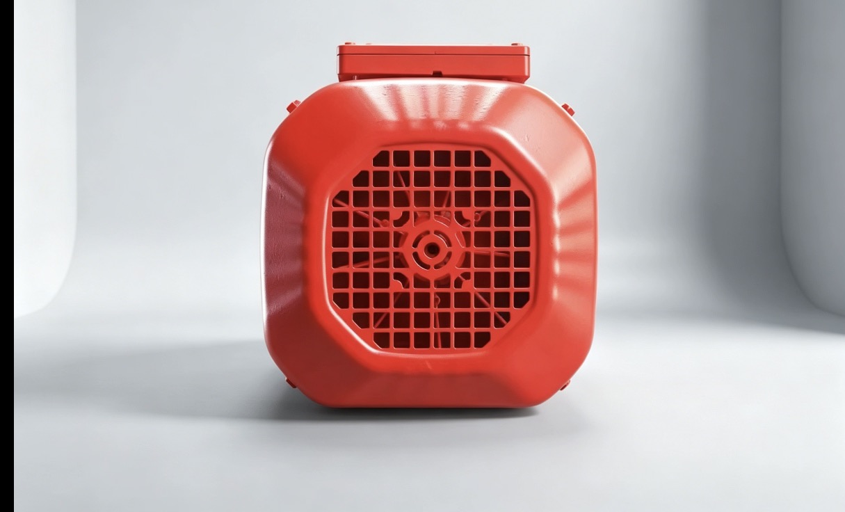
- Remove the Fan Guard: Take off the cowl at the back of the motor.
- Use a Feeler Gauge: Insert a feeler gauge between the pressure plate and the magnet body at three points around the circumference ($120^\circ$ apart).
- Adjusting the Gap:Loosen the hex nuts on the stay bolts.Turn the adjusting nuts until the feeler gauge fits snugly at the "Normal Setting" value.Ensure the gap is uniform across all points to prevent uneven wear or "dragging."Tighten the lock nuts and re-verify the gap.
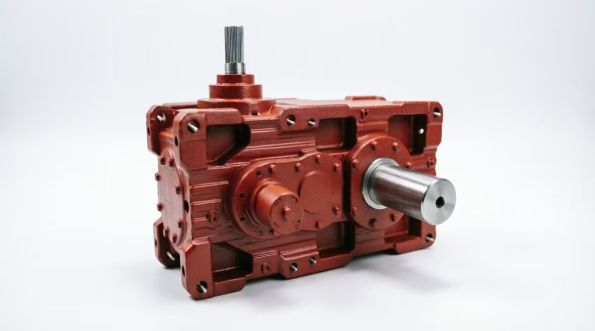
4. Mechanical Considerations for MC3RVHF06
Because this is an HF (Hollow Shaft/Flange) model, the brake performance directly impacts the gearbox internals:
- Thermal Load: If the brake drags, heat travels down the motor shaft into the gearbox input stage, potentially damaging the input oil seal.
- Shrink Disc Security: Ensure the shrink disc is tightened to the correct torque. A failing brake that "jerks" during emergency stops can put immense stress on the friction-fit connection of the HF hollow shaft.
5. Maintenance Checklist
| Task | Interval | Note |
| Check Air Gap | Every 6 months | More frequent for "inching" or high-cycle starts. |
| Inspect Lining | During gap check | Replace the brake disc if the lining is $< 2\text{mm}$ thick. |
| Oil Level | Monthly | Check the sight glass on the MC3RVHF06 housing. |
| Breather Valve | Monthly | Clean the brass breather to prevent pressure build-up. |
6. Troubleshooting the Brake/Gearbox Interface
- Motor Hums but Won't Turn: The air gap is likely over the maximum limit; the rectifier cannot release the brake.
- Delayed Braking: The air gap might be too small, or the BGE rectifier is malfunctioning.
- Grinding Noise during Braking: The brake lining is completely worn (metal-on-metal), or the gearbox input bearing is failing due to heat soak.
Do you need the specific torque values for the shrink disc bolts on your Size 06 unit, or are you looking for the wiring diagram for the brake rectifier?
CUSTOMER REVIEWS
{{commentStat.averageRating}}
{{commentStat.total}} Revirews
All({{commentStat.total}})
Images({{commentStat.imgSum}})
5 Star({{commentStat.praiseSum}})


{{item.comments}}